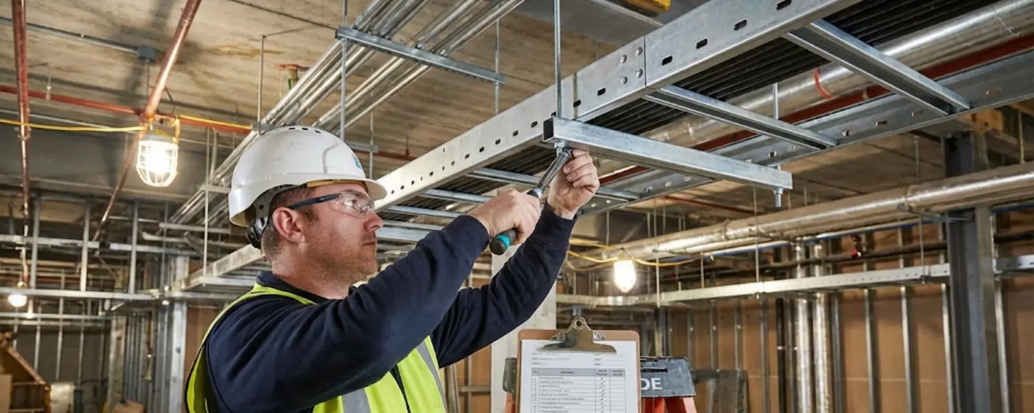
In modern industrial and commercial infrastructure, the cable management system is the silent backbone of operational efficiency. While often overshadowed by the high-tech equipment they serve, cable trays play a critical role in protecting, routing, and organizing the complex web of power and data lines that keep facilities running. However, a Cable Tray Installation is not merely a structural task; it is a precision engineering challenge governed by strict electrical codes and safety standards.
Improper installation can lead to cable damage, overheating, structural collapse, and severe safety hazards. To ensure your electrical infrastructure is robust, compliant, and future-proof, adherence to best practices is non-negotiable. Here are the five golden rules for a safe and compliant Cable Tray Installation.
Rule 1: Strictly Adhere to NEC Article 392 and NEMA VE 2 Standards
Compliance begins before the first bolt is tightened. The National Electrical Code (NEC), specifically Article 392, acts as the governing law for cable tray systems, dictating everything from permitted uses to wiring methods. Simultaneously, NEMA VE 2 provides the practical installation guidelines recognized globally as the industry standard.
Ignoring these guidelines is the fastest route to a failed inspection or a dangerous installation.
Planning is Key: Before installation begins, ensure your layout plan aligns with NEC requirements regarding accessibility and clearances.
Environmental Compatibility: Verify that the tray material (e.g., galvanized steel, aluminum, fiberglass) is suitable for the installation environment, whether it is a corrosive chemical plant or a standard commercial riser.
Rule 2: Calculate Accurate Cable Fill and Load Capacity
One of the most common failures in Cable Tray Installation is overloading. Cable trays are designed to carry a specific weight per foot (load capacity) and a specific volume of cables (fill ratio). Exceeding these limits compromises the structural integrity of the tray and leads to dangerous heat buildup in the cables.
The 40-50% Rule: As a general best practice, avoid filling a tray to 100% capacity. Most standards recommend a fill ratio of 40% to 50% to allow for air circulation and heat dissipation.
Future-Proofing: Always calculate the load with future expansion in mind. A facility rarely uses fewer cables over time; leave 25% to 30% spare capacity to accommodate future upgrades without needing a complete system overhaul.
Rule 3: Ensure Precise Support Spacing and Structural Integrity
Gravity is the enemy of a poorly supported cable tray. If supports are spaced too far apart, the tray will sag, putting stress on the cables and the joiners. Conversely, over-supporting is a waste of budget.
Follow Span Ratings: Every cable tray comes with a NEMA span rating (e.g., 8 feet, 10 feet, 20 feet). Never exceed the manufacturer’s recommended distance between supports.
Strategic Support Placement: Install supports within 2 feet (600mm) of every fitting (bends, tees, crosses) and on both sides of any expansion joint. This ensures the system remains rigid where mechanical stress is highest.
Rule 4: Master Cable Routing and Separation
A professional Cable Tray Installation is defined by how the cables are managed inside the tray. Dumping cables haphazardly leads to “spaghetti” messes that are impossible to maintain and dangerous to operate.
Segregation: Never mix high-voltage power cables with low-voltage data or control cables in the same tray without a verified divider. This prevents electromagnetic interference (EMI) that can corrupt data signals.
Bend Radius Protection: Ensure that cables are not bent sharper than their minimum bend radius when transitioning in or out of the tray. Use drop-outs or waterfall accessories to protect cable insulation from sharp metal edges.
Secure Vertical Runs: In vertical installations, gravity pulls on the copper weight inside the jacket. Cables must be securely fastened to the tray rungs at regular intervals to prevent internal damage or slippage.
Rule 5: Prioritize Grounding and Bonding
Safety is the ultimate goal. A metal cable tray system must be electrically continuous to prevent shock hazards. If a live wire touches the tray, the current must have a clear path to ground to trip the circuit breaker immediately.
Electrical Continuity: Mechanical connections (splice plates) do not always guarantee electrical continuity.
Bonding Jumpers: Install bonding jumpers (short copper wires) across expansion joints or any discontinuity to ensure the ground path is never broken.
NEC Compliance: Follow NEC Article 250.96 to ensure the tray is bonded effectively to the facility’s grounding electrode system.
By following these five golden rules, you ensure that your Cable Tray Installation is not just a support structure, but a safe, compliant, and high-performance component of your electrical infrastructure.
Frequently Asked Questions
What is the standard support span for a cable tray installation?
The support span depends on the NEMA class of the tray, but typical spans range from 8 to 20 feet (approx. 2.4m to 6m). Always check the manufacturer’s specification sheet for the exact load/span rating.
How do I calculate cable tray fill capacity?
Cable fill is calculated based on the cross-sectional area of the cables relative to the usable area of the tray. NEC Article 392 provides tables (like 392.22) to determine the allowable fill for different cable types and tray widths.
Do cable trays need to be grounded?
Yes. All metal cable trays must be grounded and bonded per NEC Article 250. This ensures that if a fault occurs, the tray can safely conduct the current to ground, tripping the breaker and preventing shock hazards.
Can I run power and data cables in the same tray?
Generally, no. Power cables can generate electromagnetic interference (EMI) that disrupts data signals. If they must share a path, they should be physically separated by a grounded metal barrier or divider within the tray.
What is the difference between NEMA VE 1 and NEMA VE 2?
NEMA VE 1 covers the manufacturing and performance standards for metal cable trays (how they are built). NEMA VE 2 is the guideline for shipping, handling, and Cable Tray Installation (how they are installed).
Why is cable separation important in trays?
Separation prevents signal interference (EMI) between power and data cables and also aids in heat dissipation. Grouping power cables too tightly can cause them to overheat, derating their ampacity.
How much space should I leave for future expansion?
Industry best practice recommends leaving at least 25% to 30% of the tray’s cross-sectional area empty during the initial installation to accommodate future cable additions without overloading the system.
What are the risks of overloading a cable tray?
Overloading can cause the tray to sag or collapse, damaging the cables and infrastructure below. It also restricts airflow, causing cables to overheat, which can melt insulation and lead to electrical fires.